In the first part of this series, we explored the hardware and electronics of an IBM LTO-6 tape drive, including its SAS connectivity, cooling system, circuit boards, and internal motor structures.
But there is another side of tape technology that I find even more interesting: the mechanical system.
Have you ever wondered how an LTO drive manages to pull a magnetic tape out of its cartridge, guide it through the equipment, and position it correctly for reading and writing?
From the outside, it seems simple. We insert a cartridge, wait for the drive to load it, and begin our backup or restore operation.
Inside the equipment, however, there are several mechanical components that must work together.
While examining this defective IBM LTO-6 drive, I took some photographs and videos of the internal mechanisms. I was particularly interested in understanding the purpose of the gears, motors, tape guides, and the small components near the read/write head.
I also noticed a possible irregularity in part of the gear assembly, which was interesting considering that the equipment had already been experiencing cartridge-loading problems.
In this second article, we’ll take a closer look at these components and understand what each one does.
As with Part 1, this is an educational hardware exploration, not a repair guide. The drive was already defective and out of warranty. Opening or servicing tape drives without manufacturer authorization can damage the equipment, affect support eligibility, and void applicable warranty coverage. Do not attempt this on working equipment.
1. The Cartridge Loading Mechanism
Let’s start with the area where everything begins: the cartridge-loading mechanism.
When an LTO cartridge is inserted into the drive, it must be correctly positioned before the tape can be extracted.
This involves mechanical guides, positioning structures, and a motor-driven loading system.
One detail worth understanding is that the cartridge-loading mechanism and the tape-threading mechanism are not exactly the same thing.
The cartridge loader is responsible for positioning and retaining the cartridge. The threading mechanism performs the next important operation: capturing the tape’s leader pin and moving it through the internal tape path.
These two processes need to work together, but they involve different movements and mechanical components.
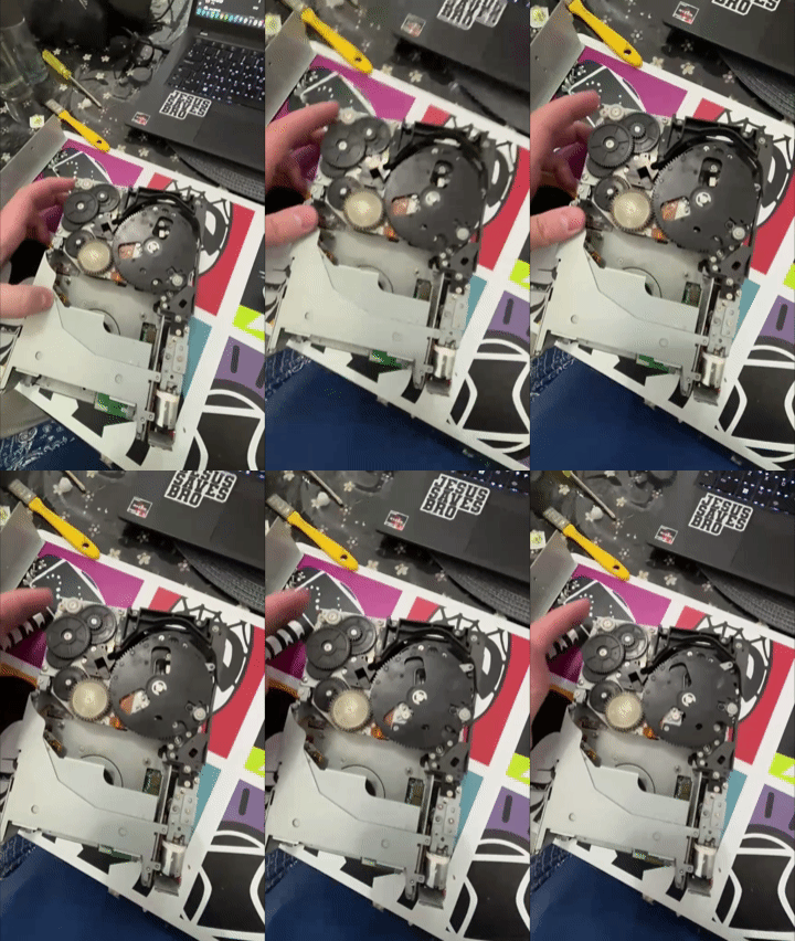
Looking at the internal assembly, we can see that the loading system contains several moving parts connected through gears and linkages.
If one of these movements cannot be completed, the drive may fail to finish its loading sequence.
This is particularly interesting in the case of the equipment used for this article, since its original problem was related to cartridge insertion and loading.


2. Gears: How Movement Is Transferred Inside the Drive
One of the first things that caught my attention was the number of gears inside the equipment.
Some are relatively small, while others form larger assemblies connected to mechanical arms and moving structures.
Their purpose is to transfer movement from a motor to another mechanical component.
In the IBM LTO drive documentation, we can find components identified as the loader motor worm gear, threader intermediate gear, and threader mechanism gear.
Although these names may sound complicated, their functions become easier to understand when we separate the different operations.
The loading mechanism positions the cartridge, while the threading mechanism moves the leader assembly along the tape path.
These mechanisms require controlled movement, and the gears help transmit the rotation generated by their motors.
A worm gear is particularly interesting because it uses a screw-like component to transmit rotation to another gear, normally changing the direction and mechanical characteristics of the movement.
In the photographs, we can see several gears of different sizes, including a large circular gear connected to a linkage.
This assembly is associated with the mechanical movement system. It should not be confused with the take-up reel where the magnetic tape itself is wound.
Something that looks like a simple plastic gear can actually be essential to completing a cartridge-loading operation.

3. The Motors That Move the Mechanism
Of course, gears need something to make them move.
And that is where the electric motors come in.
The drive uses motor-driven mechanisms for different operations, including loading the cartridge, moving the threading assembly, and controlling the reels during tape transport.
These operations have different purposes.
The cartridge loader needs to move the cartridge into the correct position, while the threading mechanism needs to capture the tape and guide it along a specific path.
The reel motors, on the other hand, are responsible for controlling the movement of the magnetic tape during normal operation.
All of this requires coordination.
A motor cannot simply rotate indefinitely without considering the position of the mechanism it is controlling.
The drive uses its internal electronics and sensor feedback to manage these movements.
One thing that I found interesting was seeing how much of the motor movement is transferred through relatively small gears.
From the outside, we hear mechanical noises when the cartridge is inserted, but we rarely think about the individual components responsible for producing those movements.

4. The Leader Pin and Leader Block Assembly
Now we get to one of my favorite parts of the LTO mechanism.
Unlike a traditional two-reel tape cassette, an LTO cartridge contains a single supply reel.
The magnetic tape remains wound inside the cartridge, and its free end is attached to a small metal component called the leader pin.
This pin is protected behind a small door in the cartridge.
When the cartridge is loaded, the drive must capture the leader pin and pull the tape out of the cartridge.
To accomplish this, the drive uses a mechanism associated with the leader block assembly, or LBA.
This assembly follows the internal threading path, bringing the tape from the cartridge toward the drive’s take-up reel.
Think about what this means.
Every time a cartridge is loaded, the drive needs to establish a mechanical connection with the tape, extract it from the cartridge, and prepare it to travel through the read/write area.
And when the cartridge is unloaded, that process needs to be reversed so that the tape returns safely to the cartridge.
The leader pin is a small component, but its role is extremely important.
Without the tape being properly captured and threaded, the drive cannot perform normal read and write operations.
In Part 3, I plan to show this process visually using a defective cartridge, which should make the relationship between the leader pin and the threading mechanism much easier to understand.


5. The Take-Up Reel: Where Does the Tape Go?
This is another part of LTO technology that I think is worth understanding.
Since the cartridge contains only one reel, where does the magnetic tape go after being pulled out?
The answer is the take-up reel.
The drive contains its own non-removable reel, which receives the tape during the threading and transport process.
The cartridge’s supply reel and the drive’s take-up reel work together to move the tape through the internal path.
The drive controls their movement to maintain appropriate tape speed and tension.
This is important because the tape is a relatively thin magnetic medium that must travel through the equipment in a controlled manner.
The drive also needs to change the direction of tape movement during normal operations.
One common misunderstanding when looking at photographs of an open drive is confusing the motor assemblies or mechanism gears with the take-up reel itself.
They are different components.
The motors generate and control movement, the gears transfer movement where required, and the reel physically receives the magnetic tape.
Once we have a defective cartridge available for the practical demonstration, this distinction will become much clearer.


6. Tape Guides and Rollers: Keeping Everything Aligned
After leaving the cartridge, the tape cannot simply move freely through the drive.
It needs to follow a precisely controlled path.
This is the purpose of the tape guides and rollers.
In the photographs, we can see several cylindrical metal components positioned around the central area of the drive.
These components are part of the tape path and help guide the magnetic media through the equipment.
The tape needs to remain correctly positioned as it moves between the supply reel, read/write head, and take-up reel.
Its alignment and tension are particularly important because LTO technology stores data on a large number of narrow tracks.
If the media does not travel through the correct path, the head may be unable to read or write reliably.
Mechanical wear, contamination, or damage to components along the tape path can potentially affect this process.
Of course, the drive also uses sophisticated electronic positioning and control systems, but the physical tape path remains essential.
Looking at these rollers helped me better understand why magnetic tape drives require such carefully designed mechanical assemblies.


7. The Read/Write Head: Where Data Meets Magnetic Tape
Now let’s talk about one of the most important components inside the drive: the read/write head.
This is where the drive physically interacts with the magnetic tape to record or retrieve information.
During a backup, the drive receives data from the host and processes them for magnetic recording.
The head then writes information onto the tape as it moves across the recording area.
During a restore or read operation, the head detects the recorded magnetic information, and the drive processes it to reconstruct the data.
LTO uses linear serpentine recording.
This means that data are written along the length of the tape in sets of parallel tracks. After one pass, the drive can reposition the head to another set of tracks and continue recording in the opposite direction.
To make this possible, the head assembly includes a positioning mechanism.
The drive also uses servo information recorded on the tape to maintain alignment between the head and the recorded tracks.
This is particularly impressive when we think about the recording density involved.
The head needs to maintain accurate positioning while the tape is moving.
In the photographs, the central tape-path assembly is visible, including the rollers and the region where the read/write head operates.
However, the individual recording elements are too small to identify reliably in these images, so I prefer to refer to the complete head area rather than claim to show each recording element.

8. The Small Brush Near the Head
There was another component that immediately caught my attention.
Near the central mechanism, I noticed a small structure that looks like a brush.
At first glance, it is easy to overlook. Compared with the motors, gears, and metal rollers, it looks like a relatively simple component.
However, IBM Ultrium drives have an integrated head-cleaning device that brushes the read/write head during cartridge loading and unloading.
This helps remove contamination that could interfere with recording or reading data.
The brush-like component visible in my photographs appears consistent with this type of mechanism, although its exact identity would require confirmation against the specific assembly documentation.
An important detail is that this integrated cleaning mechanism does not replace the dedicated LTO cleaning cartridge.
IBM recommends using a cleaning cartridge when the drive indicates that cleaning is required.
The cleaning cartridge performs a separate cleaning operation, and unnecessary cleaning cycles are not recommended.
I find this particularly interesting because we often think about cleaning cartridges as the only cleaning mechanism available in tape technology.
Seeing a small brush-like component inside the drive helps illustrate that some cleaning-related functions are also integrated into the hardware itself.

9. Sensors and Mechanical Positioning
There is another important part of the mechanical system that we cannot ignore: position detection.
A tape drive needs to know whether the cartridge and different mechanical assemblies have reached their expected positions.
This is where sensors and electronic feedback become important.
The drive uses information from its internal systems to coordinate the loading and threading sequence.
For example, it needs to determine whether the required conditions have been met before proceeding with another mechanical movement.
This is one of the reasons why diagnosing tape-drive hardware failures can be complicated.
If a motor does not complete a movement because of a mechanical problem, the resulting error may indicate that a loading operation failed.
However, the underlying issue could involve a gear, motor, sensor, or another component.
This is something worth remembering during hardware troubleshooting.
The error presented to the backup application does not always identify the specific physical component responsible for the failure.

10. A Possible Mechanical Problem in This Drive
As I mentioned at the beginning, this particular drive was already experiencing problems during cartridge insertion and loading.
While examining the side gear assembly, I noticed what appeared to be an irregular area on one of the black gears.
Some of the teeth looked unusual, and I wondered whether the component had experienced mechanical wear or damage.
Considering the original symptoms, this was an interesting observation.
A damaged gear could potentially interfere with the movement of the loading or threading mechanism, preventing the assembly from reaching the expected position.
However, I want to be careful here.
The photographs alone are not enough to confirm that the gear is damaged or that it caused the loading problem.
The appearance could also be influenced by the viewing angle, lighting, grease, or material on the surface.
A proper diagnosis would require additional inspection and appropriate technical testing.
Since my objective was educational rather than repairing the equipment, I did not attempt to establish a definitive root cause.
Still, this observation illustrates something important.
Even a small mechanical component can be critical to the operation of a tape drive.
And when we see the complete mechanism, it becomes easier to understand why a problem in one component may affect an entire loading sequence.

Final Thoughts
Before this inspection, I already understood how LTO technology worked from an infrastructure and operational perspective.
But seeing the mechanical components directly gave me a different appreciation for the technology.
The leader pin, take-up reel, gears, motors, tape guides, read/write head, and cleaning mechanism all perform different functions.
Yet they depend on one another to complete a relatively simple task from the user’s point of view: loading a cartridge and making it ready for reading or writing.
Something else that caught my attention was how small some of the critical components are.
A gear, a mechanical linkage, or a small positioning component may seem insignificant when compared with the entire drive, but it can potentially prevent the equipment from operating correctly.
This reinforces a lesson that applies to backup infrastructure in general.
We often focus on software, jobs, connectivity, and configurations, but the physical condition of the hardware remains just as important.
And now that we’ve identified the main components, I think the next step will be even more interesting.
In Part 3, the plan is to use this same defective drive and a separate damaged LTO cartridge to demonstrate the tape-loading mechanism in practice.
Instead of simply showing photographs of individual parts, we’ll observe how they interact as the tape moves through the drive, including the capture of the leader pin, the tape path, and the movement of the mechanical assembly.
I also want to take a closer look at the area where the possible gear irregularity was observed, without assuming it caused the original failure.
That should help connect everything we’ve explored in the first two articles.
See you in Part 3!